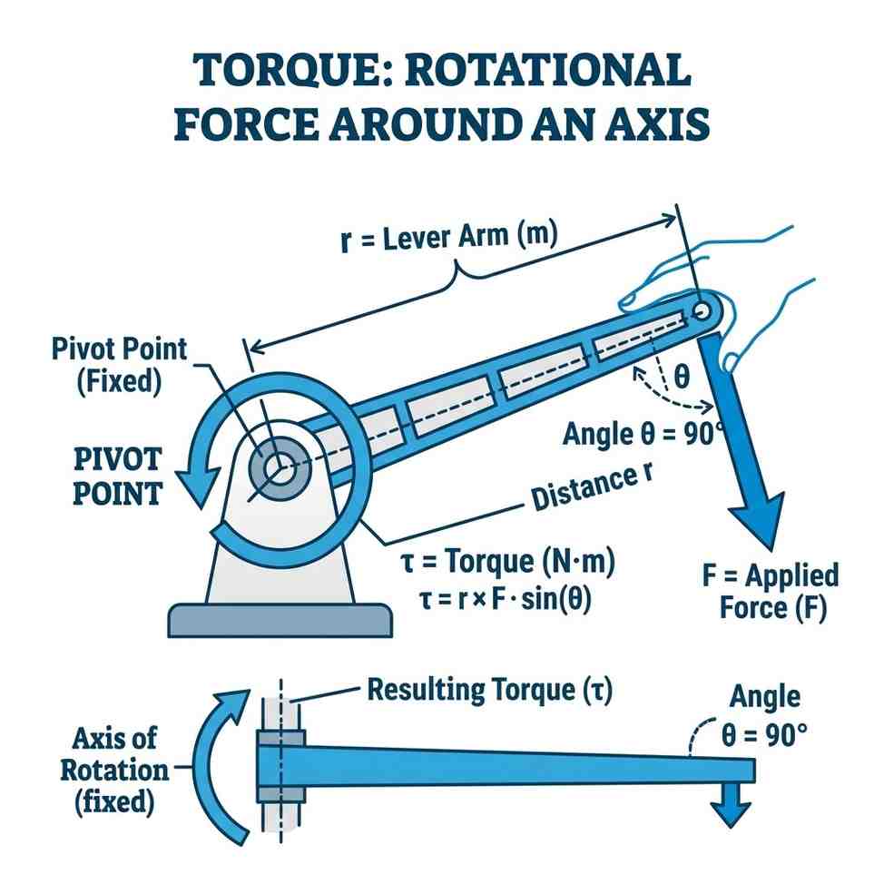
Figure 1: Torque visualized as a rotational force — the product of force magnitude and lever arm distance
Torque is one of the most fundamental concepts in all of physics and engineering — yet it's also one of the most misunderstood. Whether you're an automotive enthusiast wondering why diesel trucks have "more torque," a student studying mechanics, or a professional engineer specifying fastener tightness, understanding torque is essential.
This guide explains torque from the ground up, in plain language, with real-world examples, vector mathematics, and industrial applications that make the concepts clear for students and professionals alike.
The Fundamental Concept of Torque
Torque is rotational force — the tendency of a force to cause rotation around a fixed point (called the pivot point, fulcrum, or axis of rotation). While a linear force pushes or pulls an object in a straight line, torque makes things spin. It is the rotational equivalent of linear force.
Think of opening a door. You push the door handle (applying force), and the door rotates on its hinges. That rotational tendency is torque. And crucially, the same force applied further from the hinge produces more torque — which is why door handles are placed far from the hinges rather than close to them. This physical principle is called leverage.
Distance Matters
Doubling the distance from the pivot doubles the torque for the same force. This is why longer wrenches or breaker bars make loosening stuck bolts significantly easier with less physical effort.
Angle Matters
Force must be applied perpendicular to the lever arm (exactly 90 degrees) for maximum torque. Angled forces reduce the effective leverage, producing less rotation.
Torque ≠ Force
Torque and force are physically distinct. A small force applied at a large distance (like a long crowbar) can produce far more torque than a massive force applied close to the pivot point.
Direction & Vectors
Torque is a vector quantity with magnitude and direction (clockwise or counter-clockwise). This direction governs whether a fastener is tightened or loosened, following standard threading conventions.
The Vector Nature of Torque and the Right-Hand Rule
In vector calculus, torque is mathematically defined as the cross product of the position vector \(\vec{r}\) and the force vector \(\vec{F}\):
\(\vec{\tau} = \vec{r} \times \vec{F}\)
Because it is a cross product, the resulting torque vector \(\vec{\tau}\) is perpendicular to the plane containing the lever arm and force vectors. In physics, this vector is called an axial vector or pseudovector. It represents the axis around which rotation occurs.
To find the direction of the torque vector, engineers use the Right-Hand Rule:
1. Point the fingers of your right hand in the direction of the position vector \(\vec{r}\) (from pivot to force point).
2. Curl your fingers toward the direction of the force vector \(\vec{F}\).
3. Your thumb will naturally point in the direction of the torque vector \(\vec{\tau}\). If it points out of the page, the rotation is counter-clockwise; if it points into the page, the rotation is clockwise.
Dimensional Analysis: Torque vs. Work (Joules)
One of the most interesting details of torque physics is its unit dimensions. In SI units, both torque and work/energy are calculated as force times distance, resulting in the unit unit of **Newton-meters (N·m)**.
However, they are completely different physical concepts:
- Work (Joule) is a scalar quantity. It measures energy transferred when a force moves an object *along* a distance: \(W = F \cdot d\). The force and movement vectors are parallel.
- Torque (N·m) is a vector quantity. It measures rotational force applied at a perpendicular distance from the pivot axis: \(\tau = F \times r\). The force and distance vectors are perpendicular.
To avoid confusion, engineers always express torque in **Newton-meters (N·m)** or **pound-feet (lbf·ft)**, reserving **Joules (J)** exclusively for energy or work.
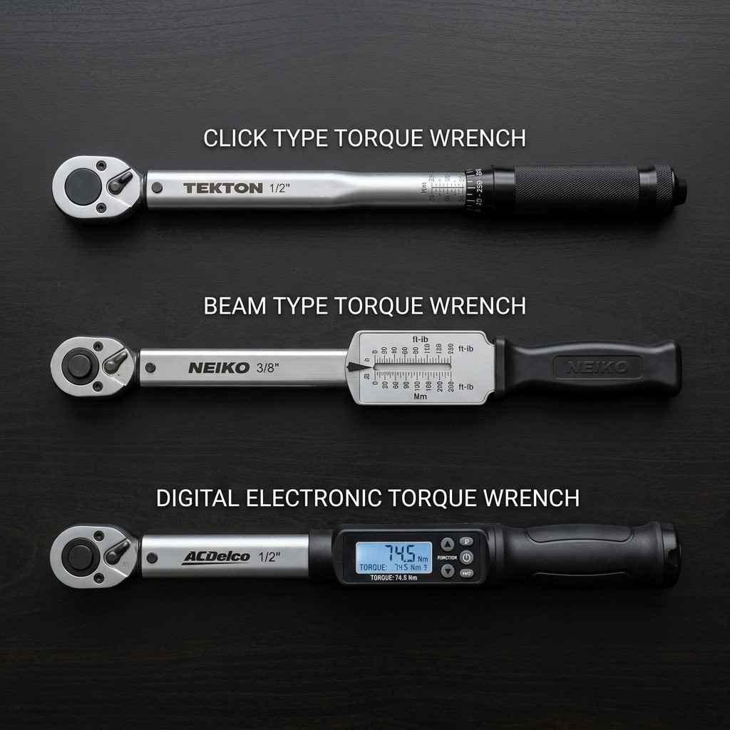
Figure 2: A wrench multiplies your applied force through leverage — the longer the handle, the greater the torque
Real-World Torque Calculations
Below are common scenario calculations showing how torque equations apply to physical systems.
🔧 Example 1: The Breaker Bar Lever
You are attempting to loosen a rusted lug nut. You apply a perpendicular force of 250 N to the end of a standard 30 cm (0.3 m) ratchet. The torque is:
τ = 250 N × 0.3 m = 75 N·m
If the nut is seized and requires 120 N·m to break free, you will fail. However, if you switch to a 60 cm (0.6 m) breaker bar and apply the same 250 N of force, the torque becomes:
τ = 250 N × 0.6 m = 150 N·m
The bolt breaks loose easily because you doubled the torque without increasing your physical effort.
🚪 Example 2: Angled Pull on a Door Handle
You push a heavy vault door at a 30-degree angle relative to the door face. You apply 100 N of force at a distance of 0.8 m from the hinges. What is the torque?
Since the force is not perpendicular, we must use the sine of the angle:
τ = 100 N × 0.8 m × sin(30°) = 80 × 0.5 = 40 N·m
If you pushed at a perfect 90-degree angle, the torque would be 80 N·m. Angled pushing wasted half of your force.
⚙️ Example 3: Gearbox Torque Multiplication
An electric motor produces 10 N·m of torque at 3,000 RPM. This motor is connected to a 5:1 gear reduction system (input turns 5 times for every 1 output turn). Assuming 100% mechanical efficiency, what is the output torque?
A reduction gearbox multiplies torque by the ratio while reducing speed by the same ratio:
Output Torque = 10 N·m × 5 = 50 N·m
Output Speed = 3,000 RPM ÷ 5 = 600 RPM
Standard Units of Torque
Depending on your region and industry, different units are used to measure torque:
- Newton-meter (N·m): The standard SI unit, used globally for automotive, aerospace, and robotics specifications.
- Pound-force foot (lbf·ft): The Imperial standard, widely used in the United States and United Kingdom for vehicle engine specs and mechanical tools.
- Kilogram-force meter (kgf·m): An older metric unit occasionally found in legacy European or Asian service manuals.
- Pound-force inch (lbf·in): Used for small fasteners (electronics, bicycle parts, valve covers) where precision is critical and standard foot-pound scales are too coarse.
- Newton-millimeter (N·mm): Standard unit in precision mechanical design, micro-optics, and medical device manufacturing.
Torque vs. Horsepower: The Dynamic Engines
In the automotive world, torque and horsepower are constantly compared. A simple explanation clarifies their roles:
- Torque is the work-capacity force of the engine. It is what launches a car from a stop and pulls heavy loads up hills.
- Horsepower is the rate at which that work is performed. It represents the combination of torque and engine speed (RPM), determining top speed and acceleration at high speeds.
The mathematical relationship is defined by the following imperial equation:
Horsepower = (Torque in lbf·ft × RPM) ÷ 5,252
This means torque and horsepower curves always cross at exactly 5,252 RPM on a standard dyno graph. A diesel engine produces massive torque at low RPM (ideal for trucks), while a sports car engine revs high to maximize horsepower despite moderate torque limits.
Torque in Fastener Engineering
Applying torque to bolts is a critical assembly task. When you tighten a bolt, the torque rotates the threads, forcing the bolt to stretch slightly. This stretch acts like a stiff metal spring, creating a clamping force (called **preload**) that holds components together.
If you apply too little torque, the bolt may work loose under vibration. If you apply too much torque, the bolt stretches past its elastic limit (yielding) and can snap. This is why engineers specify exact torque limits for structural connections.